The Don Young Rail Motor
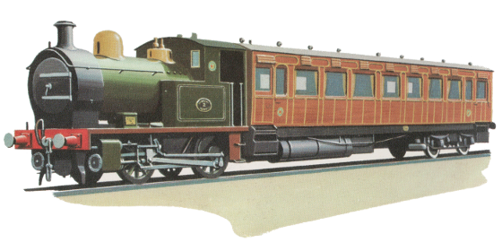
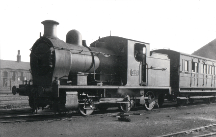
Rhymney Railway Rail Motor
Introduction
I had originally planned on building a 3½" gauge Tich as a first live steam locomotive. Billed as an ideal beginner's loco and even the subject of a book entitled "Simple model locomotive building introducing LBSC's Tich", this attractive little engine seemed like the perfect introduction to the hobby. There has, however, been a considerable amount of debate in online forums and in the model engineering press as to just how suitable Tich actually is for the beginner.
The prevailing opinion seems to be that due to its small size, building this diminutive engine would be more akin to watchmaking than model engineering. And once complete, the tiny fire requiring constant attention, would not make it an easy engine for the inexperienced driver to learn on. Besides which, in the end, after all that work, one is left with a loco that will barely pull the driver and not much else.
In search of an alternative design for an introductory model, paging through old copies of Model Engineer Magazine I came across Don Young's Rail Motor. A 5" gauge 0-4-0 loco which reputedly is an excellent choice for the beginner - relatively easy to build, easy to drive, and by all accounts an excellent performer on the track. In addition, for me, it has the added appeal of it being a model of a real-world prototype rather than a freelance design.
The prototype
The model
Two variants of the model were described in Model Engineer, dubbed No 1 and No 2 respectively.
The No 1 engine drawn by Don from photographs of the
Rhymney Railway Rail Motor was intended as a close to scale model of the engine unit, substituting a tender for the rail motor carriage.
While the No 2 engine as a simplified freelance redesign of the locomotive speculating as to what it may have looked like as a tank loco.
In August 1982, details of a third variant dubbed Railmotor No 3, were published by Steve Titley and Harry Lumb in Don Young's own magazine - Locomotives Large and Small (LLAS). This combined a No 1 boiler with a No 2 chassis to create a representative model of the Southern Railway S14 0-4-0 tank engine.
Following on from the success of the 5" gauge locomotives, Don subsequently produced two 7¼/7½" gauge designs. Namely Tug, a simple but robust tank engine, as well as the close to scale Rhymney Rail Motor once again with a tender replacing the rail motor carriage. Construction for both engines was serialised in LLAS. For the newcomer to model engineering, either of these handsome locomotives would make a compact but powerful introduction to the larger gauges.
For myself, having decided to build in 5" gauge, and at the time not yet being aware of No 3, it simply came down to choosing between the No 1 or the No 2 engines. It was not an easy decision as both of these little locomotives have tremendous appeal. Yet, despite the No 2 being the simpler of the two engines to build, and also having the advantage of being a compact self-contained unit, the No 1 won out based on a combination of looks and my preference for a model of a real-world prototype.
Summary of Rail Motor designs
| Gauge | Length | Wheel Dia | Boiler Dia | Cylinder Bore | |
|---|---|---|---|---|---|
| Railmotor 1 | 5" | 21.5" (exc tender) | 3.5" | 4.75" | 1.25" |
| Railmotor 2 | 5" | 21.5" | 3.5" | 4" | 1.0625" |
| Railmotor 3 | 5" | 19" | 3.5" | 4.75" | 1.25" |
| Rhymney Rail Motor | 7¼/7½" | 55" (inc tender) | 5.25" | 7.25" | 1.75" |
| Tug | 7¼/7½" | 30" | 5.25" | 7.25" | 1.75" |
Bibliography
The construction series for Railmotor No 1 and No 2 was serialised in Model Engineer between April 1968 and March 1969.
Railmotor No 3 along with the two 7¼/7½" engines were later designs published in Locomotives Large and Small (LLAS).
Railmotor 1 & 2 - ME
| Volume | Issue | Date | Page | Article |
|---|---|---|---|---|
| 134 | 3342 | 05.04.1968 | 325 | Building 5 in. Gauge Rail-Motor Locomotives |
| 134 | 3343 | 19.04.1968 | 389 | Building 5 in. Gauge Rail-Motor Locomotives |
| 134 | 3344 | 03.05.1968 | 442 | Building 5 in. Gauge Rail-Motor Locomotives |
| 134 | 3345 | 17.05.1968 | 484 | Building 5 in. Gauge Rail-Motor Locomotives |
| 134 | 3346 | 07.06.1968 | 553 | Building 5 in. Gauge Rail-Motor Locomotives |
| 134 | 3347 | 21.06.1968 | 610 | Building 5 in. Gauge Rail-Motor Locomotives |
| 134 | 3348 | 05.07.1968 | 640 | Building 5 in. Gauge Rail-Motor Locomotives |
| 134 | 3349 | 19.07.1968 | 704 | Building 5 in. Gauge Rail-Motor Locomotives |
| 134 | 3350 | 02.08.1968 | 753 | Building 5 in. Gauge Rail-Motor Locomotives |
| 134 | 3351 | 16.08.1968 | 811 | Building 5 in. Gauge Rail-Motor Locomotives |
| 134 | 3352 | 06.09.1968 | 862 | Building 5 in. Gauge Rail-Motor Locomotives |
| 134 | 3353 | 20.09.1968 | 912 | Two 5 in. gauge "Push and Pull" locomotives |
| 134 | 3354 | 04.10.1968 | 958 | Two 5 in. gauge "Push and Pull" locomotives |
| 134 | 3355 | 18.10.1968 | 1016 | Two 5 in. gauge "Push and Pull" locomotives |
| 134 | 3356 | 01.11.1968 | 1062 | Building 5 in. Gauge Rail-Motor Locomotives |
| 134 | 3357 | 15.11.1968 | 1122 | Building 5 in. Gauge Rail-Motor Locomotives |
| 134 | 3358 | 06.12.1968 | 1174 | Building 5 in. Gauge Rail-Motor Locomotives |
| 134 | 3359 | 20.12.1968 | 1231 | Two 5 in. gauge "Push and Pull" locomotives (drawings pg 1230) |
| 135 | 3360 | 03.01.1969 | 30 | Two 5 in. gauge "Push and Pull" locomotives |
| 135 | 3361 | 17.01.1969 | 81 | Two 5 in. gauge "Push and Pull" locomotives |
| 135 | 3362 | 07.02.1969 | 124 | Two 5 in. gauge "Push and Pull" locomotives |
| 135 | 3363 | 21.02.1969 | 194 | Two 5 in. gauge "Push and Pull" locomotives |
| 135 | 3364 | 07.03.1969 | 235 | "Push and Pull" locomotives (final tender details) |
Additional Construction Notes - ME
After the conclusion of the construction series, additional construction notes were included with some of Don's subsequent designs.
| Volume | Issue | Date | Page | Article |
|---|---|---|---|---|
| 136 | 3397 | 17.07.1970 | 694 | No. 1 Rail Motor progress report - lubricator drive error |
| 136 | 3403 | 16.10.1970 | 999 | The Author's Rail-motor progress to date - photo |
| 136 | 3404 | 06.11.1970 | 1054 | No. 1 Rail Motor - link trunnion error |
| 136 | 3405 | 20.11.1970 | 1106 | No. 1 Rail Motor lubricator drive - photo |
Railmotor 3 - LLAS
| Issue | Date | Page | Article |
|---|---|---|---|
| 12 | August 1982 | 23 | No 3. Railmotor |
Rhymney Rail Motor and Tug in 7¼/7½ in. gauge - LLAS
| Issue | Date | Page | Article |
|---|---|---|---|
| 41 | Nov 1989 | 29 | Rhymney Rail Motor and Tug - Part 1 |
| 42 | Feb 1990 | 25 | Rhymney Rail Motor and Tug - Part 2 |
| 43 | May 1990 | 25 | Rhymney Rail Motor and Tug - Part 3 |
| 44 | Aug 1990 | 25 | Rhymney Rail Motor and Tug - Part 4 |
| 45 | Nov 1990 | 25 | Rhymney Rail Motor and Tug - Part 5 |
| 46 | Feb 1991 | 25 | Rhymney Rail Motor and Tug - Part 6 |
| 47 | May 1991 | 25 | Rhymney Rail Motor and Tug - Part 7 |
| 48 | Aug 1991 | 25 | Rhymney Rail Motor and Tug - Part 8 |
Miscellaneous articles
Listed here are some articles that have been published in Model Engineer (ME), Engineering In Miniature (EIM), and Locomotives Large and Small (LLAS) that may be of interest to potential constructors.
| Volume | Issue | Date | Page | Article | |
|---|---|---|---|---|---|
| ME | 141 | 3521 | 19.09.1975 | 903 | No 1. Rail motor refit |
| ME | 142 | 3543 | 20.08.1976 | 800 | A 5 in. Gauge "Rail-Motor" built by Anthony Vince |
| ME | 175 | 4002 | 06.10.1995 | 426 | Don Young Memorial Rally - Photo of Railmotor built by Don Young |
| ME | 183 | 4101 | 27.08.1999 | 278 | 1999 Don Young Designs Rally - No 1. Railmotor, photograph |
| ME | 200 | 4325 | 09.05.2008 | 553 | Rail-Motor boiler - My first boiler |
| ME | 200 | 4327 | 06.06.2008 | 679 | Rail-Motor boiler - My first boiler |
| ME | 201 | 4329 | 04.07.2008 | 26 | Rail-Motor boiler - My first boiler |
| ME | 201 | 4333 | 29.08.2008 | 259 | Rail-Motor boiler - My first boiler |
| ME | 201 | 4335 | 26.09.2008 | 382 | Rail-Motor boiler - My first boiler |
| EIM | 28 | 10 | Apr 2007 | 330 | Rhymney Railmotor |
| LLAS | 18 | Feb 1984 | 34 | Reflections on a Rail Motor |
Modifications and errors
- Model Engineer #3397 17 July 1970 pg694:
The frame stay immediately behind the cylinders fouls the lubricator drive. Invert the stay and then slightly alter the drive from the feed pump eccentric, while shortening the drive arm on the lubricator by 1/4".
A photograph of this modification appears in Model Engineer #3405 20 Nov 1970 pg1106.
Alternatively, this frame stay be omitted completely as per point two below. - The drawings I received from Reeves had a barely legible handwritten note alongside the frame stay mentioned above:
"This stretcher fouls lubricator drive. Suggest omit as frames well stayed without this stay."
A second handwritten note on the same drawing:
"P - Easier to fit s/box if this dimension reduced to 1/4". This applies to the distance between the top of the frames and the smokebox mounting holes also annotated by a "P". - Model Engineer #3404 6 Nov 1970 pg1054:
The link trunnion 9/32" dimension should read 13/32". This supersedes the error reported around the motion plates in ME #3397 17 July 1970 pg695 which should be ignored. - As Don was unable to determine the correct shape of the chimney cap from the photographs that he had available at the time, he drew two variants for the No 1 engine. The one shown on the front view with a convex top curve, while on the side view it is shown with a concave top curve. Although a minor detail, for the sake of fidelity to the original, the concave shape as shown on the side view is apparently the correct one.
-
Some suggestions have appeared on the Model Engineer Forum:
- The No 1 cylinder bores should not be opened out beyond that specified for the No 2 cylinders i.e no larger than 1 1/16" in diameter.
- For the No 3 Railmotor the turret bush should be positioned on the boiler so as not to foul the plate-work when this is erected.
- The mounting holes for the stretcher fixed to the front bottom corner of the frames share the same holes as three of the cylinder bolts which could pose difficulties when trying to tighten these.